Maax Shower Door Installation: A Comprehensive Guide
Embarking on a Maax shower door installation? Access detailed installation guides like maax-install-guide-10042723-connect-alcove-en-fr.
These PDF resources, alongside technical drawings (maax-door-tech-draw-connect-en-fr), ensure a smooth, professional outcome for your bathroom renovation project;
Understanding Maax Shower Door Models
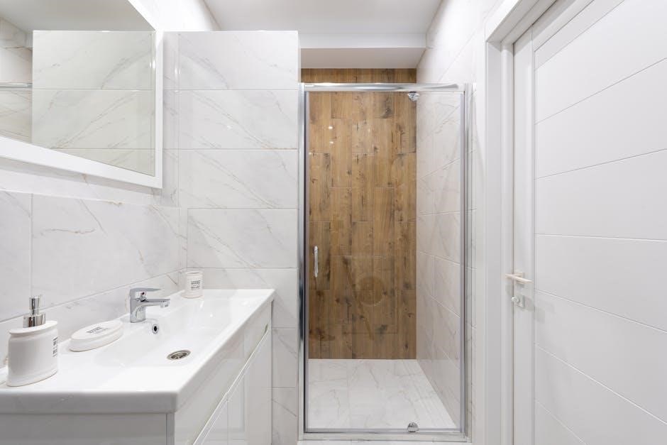
Maax offers a diverse range of shower door models, each with unique installation nuances. The Connect Alcove, frequently documented in installation guide maax-install-guide-10042723-connect-alcove-en-fr, is a popular choice known for its straightforward assembly.
Conversely, the Incognito Sliding Door, showcased in a helpful installation video by MAAX Bath Inc. (12:48 duration), requires precise alignment of its sliding mechanism. The elegant Duel Frameless Shower Door, boasting square hardware and a chrome frame, demands careful handling of its glass panels, as highlighted in related resources.
Understanding these distinctions is crucial; always consult the specific installation instructions PDF corresponding to your Maax model (e.g., 10041309-XXX-001 for shower doors, 10041309-XXX-002 for tub doors). Proper model identification ensures a successful and secure installation.
Locating the Correct Installation PDF
Finding the right Maax shower door installation PDF is paramount. Begin by visiting the official MAAX Bath Inc. website and navigating to their support or downloads section. Utilize precise search terms like your specific model number (e.g., 10041309-XXX-001) alongside “installation guide” or “instructions”.
Resources like maax-install-guide-10042723-connect-alcove-en-fr are often directly available for download. Alternatively, a broader web search incorporating “Maax” and your model name can yield results from authorized retailers or installation support forums.
Crucially, verify the PDF’s authenticity and relevance to your exact shower door model before proceeding. Incorrect instructions can lead to improper installation and potential safety hazards. Always prioritize official Maax documentation for accurate guidance.
Essential Tools for Installation
Successful Maax shower door installation demands the right tools. A standard toolkit should include a measuring tape, level (essential for plumb and square alignment), and a silicone gun with appropriate sealant for waterproofing. Screwdrivers (various sizes) and a drill with suitable bits are crucial for securing components.
Depending on the model, you may also require a glass suction cup for handling doors, and potentially shims to fine-tune alignment. The installation PDF will often specify screw sizes – like the 4mm x 25mm screws (10068633-XXX-600) – so have those readily available.
Safety first: wear safety glasses and gloves throughout the process. Having a helper is highly recommended, especially when lifting and maneuvering glass panels. A utility knife is useful for opening packaging and trimming sealant.
Safety Precautions Before You Begin
Prioritizing safety is paramount during Maax shower door installation. Always wear safety glasses to protect your eyes from glass shards or debris. Work gloves are essential to prevent cuts from glass edges and hardware. Ensure the work area is well-lit and free of obstructions to avoid trips and falls.
Handling glass requires extreme caution. The installation PDF doesn’t explicitly detail glass handling, but using glass suction cups is highly recommended for safe maneuvering. A helper is invaluable, especially when lifting and positioning heavier door panels.
Be mindful of electrical outlets near the installation area and avoid contact with water. Read and understand all instructions within the Maax guide before commencing work. Proper preparation minimizes risks and ensures a secure, lasting installation.
Step-by-Step Installation Process
Follow the Maax installation PDF closely for a successful outcome. Watch the installation video for visual guidance, especially for tub and shower doors, simplifying assembly.
Step 1: Unboxing and Parts Verification
Begin your Maax shower door installation by carefully unboxing all components. Referencing your specific model’s installation PDF (like maax-install-guide-10042723-connect-alcove-en-fr) is crucial at this stage.
Meticulously verify that all listed parts are present. Common components include glass panels, vertical supports, top and bottom rails, hinges, screws (4mm x 25mm ⏤ 10068633-XXX-600), and seals.
Compare the physical parts against the parts list within the PDF. Note any discrepancies immediately.
Inspect each item for damage incurred during shipping. Document any damage with photographs before proceeding. This documentation will be vital if you need to file a claim or request replacements. A thorough parts verification prevents frustrating delays later in the installation process, ensuring a smooth and efficient experience.
Don’t discard the packaging until you’ve confirmed all parts are accounted for and undamaged!
Step 2: Preparing the Shower Opening
Before commencing installation, carefully prepare the shower opening, guided by your model’s installation PDF. Ensure the walls are plumb, level, and structurally sound. Any existing soap dishes or fixtures should be removed.
Clean the surfaces thoroughly, removing any debris, old caulk, or residue. A clean surface ensures proper adhesion of the shower door components.
Verify the opening’s dimensions against the specifications detailed in the PDF. Precise measurements are critical for a proper fit.
If tiling is present, inspect the grout for cracks or damage and repair as needed. A stable and even surface is essential.
Consider applying a bead of silicone caulk along the edges of the opening to create a watertight seal. This preventative measure, often suggested in Maax guides, minimizes potential leakage issues during and after installation.
Step 3: Installing the Base/Threshold
Referencing your Maax shower door’s installation PDF is crucial for correctly installing the base or threshold. Begin by applying a generous bead of silicone caulk along the floor where the base will sit, ensuring a watertight seal.
Carefully position the base within the shower opening, aligning it precisely with the walls. Use shims if necessary to achieve a level surface, as indicated in the PDF instructions.
Secure the base using the screws provided, tightening them firmly but avoiding over-tightening, which could damage the material. The PDF will specify the correct screw type – often 4mm x 25mm (10068633-XXX-600).
Double-check the level of the base in both directions. A properly leveled base is fundamental for preventing water leakage and ensuring smooth door operation. Consult the Maax guide for specific leveling tolerances.
Allow the caulk to cure completely before proceeding to the next step, as per the PDF’s recommended drying time.
Step 4: Attaching the Vertical Supports
Consult your Maax shower door installation PDF for precise instructions on attaching the vertical supports. Typically, these supports are secured to the base and the wall, providing structural integrity for the entire assembly.
Begin by aligning the vertical supports with the pre-drilled holes in the base. Use appropriate screws – often 4mm x 25mm (10068633-XXX-600) – as detailed in the PDF, and tighten them securely.
Next, position the supports against the wall, ensuring they are plumb (perfectly vertical). Use shims if needed to compensate for any wall irregularities, referencing the PDF for acceptable tolerances.
Secure the supports to the wall using screws appropriate for your wall type (not always provided). The Maax guide will indicate the recommended screw length and type.

Verify the stability of the vertical supports before proceeding. A solid foundation is crucial for proper door alignment and function, as outlined in the installation PDF.
Step 5: Installing the Top Rail
Refer to your specific Maax shower door installation PDF for detailed guidance on top rail installation, as procedures vary by model (Connect Alcove, Incognito Sliding, Duel Frameless). This rail provides crucial upper support and alignment.
Carefully position the top rail onto the vertical supports, ensuring a snug fit. The PDF will illustrate the correct orientation and alignment points. Some models may require silicone sealant between the rail and supports for a watertight seal.
Secure the top rail using the screws specified in the PDF – typically, these are similar to those used for the vertical supports. Ensure screws are tightened evenly to avoid warping or stressing the rail.
Double-check the rail’s level using a spirit level. A level top rail is essential for smooth door operation and prevents water leakage, as highlighted in the installation PDF.
Confirm all connections are secure before moving on. A properly installed top rail forms the backbone of the shower enclosure, as detailed in the Maax documentation.

Door Installation
Consult your Maax shower door installation PDF for model-specific door attachment instructions. Videos demonstrate the process, ensuring correct hinge placement and alignment.
Step 6: Installing the Hinges
Carefully review your Maax shower door installation PDF before commencing hinge installation. The PDF will detail the specific hinge type for your model – crucial for correct attachment. Typically, hinges are secured to both the door and the fixed panel or wall using screws, often 4mm x 25mm as indicated in some documentation (10068633-XXX-600).
Ensure the hinges are aligned precisely according to the PDF’s diagrams; misaligned hinges will cause door operation issues. Pre-drilling pilot holes is often recommended, especially when working with tile, to prevent cracking. Tighten screws securely, but avoid over-tightening, which could damage the glass or frame.
The installation PDF may illustrate specific torque requirements. Pay close attention to the orientation of the hinges – top and bottom hinges often differ. Refer to installation videos (MAAX Bath Inc. provides examples) for visual guidance, supplementing the written instructions.
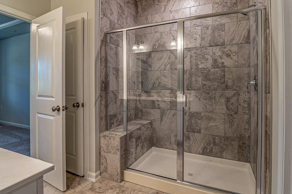
Step 7: Attaching the Shower Doors
Consult your Maax shower door installation PDF for model-specific instructions on door attachment. This step usually involves carefully lifting the door and aligning it with the installed hinges. The PDF will illustrate the correct orientation and positioning of the door within the frame.
Typically, the door is secured to the hinges using screws, ensuring a snug but not overly tight fit. Avoid forcing the door, as this could damage the hinges or glass. Some models, like the Duel frameless shower door, feature specific hardware requiring precise alignment.

Refer to the PDF’s diagrams for screw placement and tightening sequences. Installation videos from MAAX Bath Inc. can provide valuable visual guidance. Double-check that the door swings freely and smoothly before proceeding. A bifold shower door installation, as shown in DIY guides, may require extra care during this phase.
Step 8: Adjusting Door Alignment
Your Maax shower door installation PDF is crucial for precise door alignment. Most models feature adjustable hinges allowing for fine-tuning. Begin by checking for even gaps around the door perimeter; uneven gaps indicate misalignment.
The PDF will detail how to access and adjust the hinge screws, typically using an Allen wrench or screwdriver. Small adjustments are key – avoid over-tightening, which can strain the hinges. For sliding doors like the Incognito, ensure smooth gliding along the track, referencing the PDF for track adjustment procedures.
If alignment issues persist, revisit earlier steps, ensuring the base and vertical supports are perfectly plumb. MAAX customer support, detailed in installation resources, can offer assistance. A properly aligned door prevents leaks and ensures long-term functionality, as highlighted in various installation guides.

Specific Model Considerations
Maax installation PDFs vary by model – Connect Alcove, Incognito sliding doors, and Duel frameless designs each require unique attention to detail during assembly.
Maax Connect Alcove Installation
The Maax Connect Alcove shower door installation benefits greatly from utilizing the specific maax-install-guide-10042723-connect-alcove-en-fr PDF. This document provides a comprehensive, step-by-step walkthrough tailored to this popular model.
It details parts verification, crucial for ensuring all components – including screws (4mm x 25mm, identified as 10068633-XXX-600 in documentation) – are present before commencing. The PDF emphasizes preparing the shower opening correctly, focusing on achieving a level and plumb surface for optimal door function.
Pay close attention to the base/threshold installation, as this forms the foundation for the entire unit. The guide illustrates proper alignment and sealing techniques to prevent future water leakage. Furthermore, the Maax Connect Alcove installation PDF offers visual aids and diagrams, simplifying complex steps and ensuring a secure, watertight installation. Referencing the technical drawings alongside the guide is highly recommended.
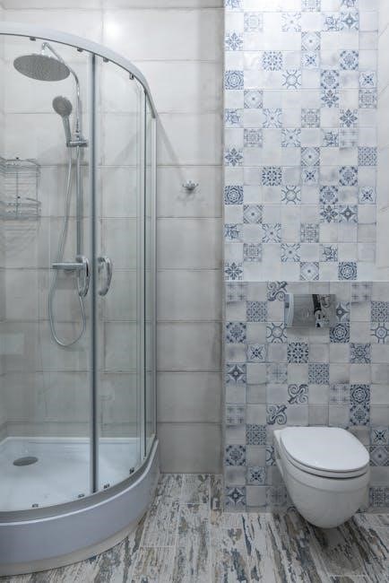
Maax Incognito Sliding Door Installation
Installing the Maax Incognito sliding shower door is streamlined with access to dedicated installation resources. While a specific PDF document number wasn’t directly provided, searching for “Maax Incognito installation” will yield relevant guides.
These guides, often available as downloadable PDFs, detail the unique aspects of this sliding door model. Key areas covered include precise track alignment, crucial for smooth door operation, and proper roller installation. The instructions emphasize careful handling of the glass panels to prevent damage during the process.
Maax provides a helpful installation video demonstrating the process step-by-step (MAAX Bath Inc. – 12:48). This visual aid complements the PDF, clarifying potentially tricky maneuvers. Remember to verify all parts are present before starting and follow the sealing recommendations to avoid water leakage.
Maax Duel Frameless Shower Door Installation
The Maax Duel frameless shower door installation benefits from detailed PDF guides, ensuring a sleek and modern bathroom upgrade. This model, known for its square hardware and chrome frame, requires precise installation for optimal performance.
While a specific PDF document number isn’t explicitly stated, searching for “Maax Duel installation” will locate the necessary resources. These guides focus on the unique challenges of frameless doors, including accurate wall alignment and secure glass panel attachment.
Pay close attention to the instructions regarding the use of appropriate sealants to prevent leaks. The PDF will outline the correct screw types (4mm x 25mm – 10068633-XXX-600) and their placement. A DIY guide can simplify the process, offering step-by-step assistance for a professional finish.

Troubleshooting Common Issues
Facing problems? Refer to the Maax installation PDF for solutions to door alignment, water leakage, and hinge adjustments. Detailed diagrams aid resolution!
Door Alignment Problems
Experiencing misalignment with your Maax shower door? The official Maax installation PDF is your primary resource for diagnosing and rectifying these issues. Often, slight adjustments to the hinges are all that’s needed to achieve a smooth, even closure.
The PDF provides detailed diagrams illustrating the hinge adjustment mechanisms specific to your model – whether it’s a Connect Alcove, Incognito Sliding door, or Duel Frameless design. Carefully review the section pertaining to hinge placement and tightening procedures.
Incorrectly tightened screws are a frequent culprit. Ensure all hinge screws are snug, but not over-tightened, as this can distort the frame. If the door still binds, double-check the vertical supports are plumb and securely fastened to the wall. The installation guide emphasizes the importance of a level base for optimal door function. Remember to consult the technical drawings within the PDF for precise measurements and tolerances.
Water Leakage Issues
Encountering water leakage after installing your Maax shower door? Your Maax installation PDF is crucial for pinpointing the source and implementing effective solutions. Common leak points include the base/threshold, door seals, and hinge connections.
The PDF details the proper application of silicone sealant around the base and vertical supports. Ensure a continuous, watertight bead is applied, following the diagrams provided. Inspect the door seals for any damage or improper seating; replacement seals are often available through Maax customer support.
For sliding doors, verify the overlapping panels are correctly aligned. The installation guide stresses the importance of a level threshold to prevent water from escaping. If leaks persist, re-examine the hinge connections, ensuring they are securely fastened and haven’t compromised the door’s seal. Refer to the technical drawings within the PDF for detailed component placement and sealing recommendations.
Hinge Adjustment Difficulties
Struggling with hinge adjustments during or after your Maax shower door installation? Your Maax installation PDF is your primary resource for navigating these challenges. The PDF provides detailed diagrams illustrating the hinge adjustment mechanisms specific to your model – Connect, Incognito, or Duel frameless.
Often, difficulties arise from improperly tightened screws or misalignment during the initial installation. The PDF emphasizes the importance of loosening screws slightly to allow for smooth adjustments. Carefully follow the step-by-step instructions for fine-tuning the door’s alignment, ensuring it swings freely and seals correctly.
If you encounter resistance, double-check the technical drawings within the PDF to confirm correct component orientation. Remember, the goal is to achieve a flush fit and prevent binding. Maax customer support, referenced in the PDF, can offer further assistance if adjustments remain problematic.
Maax Installation Resources
Locate essential resources like maax-install-guide-10042723-connect-alcove-en-fr and technical drawings. High-resolution images further simplify your Maax shower door project.
Accessing Technical Drawings
Detailed technical drawings are crucial for a successful Maax shower door installation, supplementing the installation guides like maax-install-guide-10042723-connect-alcove-en-fr. These drawings, often available as PDF documents (maax-door-tech-draw-connect-en-fr), provide precise measurements and component layouts.
Locating these drawings typically involves visiting the official Maax website and navigating to the support or downloads section. You’ll likely need your specific model number – often found on the original packaging or a sticker on the door itself – to pinpoint the correct documentation.
These drawings illustrate everything from screw placement and glass panel dimensions to the proper alignment of the top rail and base. They are invaluable for understanding the intricacies of your particular Maax shower door model, ensuring accurate assembly and a watertight seal. Don’t hesitate to utilize these resources!
Utilizing High-Resolution Images
Complementing the Maax shower door installation instructions PDF and technical drawings, high-resolution images are an invaluable asset. These visuals, often found alongside the documentation, offer a clear, detailed view of each assembly step and component. They’re particularly helpful for identifying specific parts and understanding their correct orientation.
Accessing these images usually occurs through the Maax website’s support section, often labeled as “HighRes…” or within the model-specific documentation. They provide a visual guide, clarifying any ambiguities that might arise from the written instructions or technical drawings.
Carefully studying these images before and during installation can significantly reduce errors and ensure a professional finish. They showcase proper alignment, screw placement, and the overall aesthetic of the completed installation, helping you achieve a flawless result.
Maax Customer Support Contact Information
While the Maax shower door installation instructions PDF provides comprehensive guidance, direct support can be crucial for resolving specific issues. Maax offers various channels to connect with their customer support team, ensuring assistance is readily available throughout your installation process.
For immediate assistance, consider visiting the official Maax Bath Inc. website. Look for a “Contact Us” or “Support” section, typically containing a phone number and email address. Online chat support may also be available during business hours.
When contacting support, have your model number and a copy of the installation instructions PDF readily available. This allows the representative to quickly understand your specific situation and provide tailored assistance. Don’t hesitate to utilize these resources for a smooth and successful installation.
Post-Installation Maintenance
Following the Maax shower door installation instructions PDF, regular cleaning and preventative maintenance are vital. This ensures longevity and preserves the door’s pristine appearance.
Cleaning and Care Instructions
Maintaining your newly installed Maax shower door is crucial for lasting brilliance. Referencing your Maax shower door installation instructions PDF will highlight specific glass care recommendations, but generally, a mild soap and water solution is best.
Avoid abrasive cleaners, scouring pads, or harsh chemicals, as these can damage the glass coating and metal finishes. Regular wiping down after each shower prevents water spot buildup and soap scum. For stubborn stains, a vinegar and water mixture can be effective, but always test in an inconspicuous area first.
Pay attention to the hinges and rollers, ensuring they are free of debris and lubricated periodically. This maintains smooth operation and prevents wear and tear. Following these simple cleaning and care instructions, detailed in your installation guide, will keep your Maax shower door looking its best for years to come.
Preventative Maintenance Tips
Proactive care, as outlined in your Maax shower door installation instructions PDF, extends the life of your shower door. Regularly inspect the seals and caulking around the door and base for any signs of cracking or deterioration; re-caulk as needed to prevent leaks.
Periodically check the screws and hardware, tightening them if they become loose. This ensures the door remains securely installed and aligned. Addressing minor issues promptly prevents them from escalating into larger, more costly repairs.
Consider applying a water repellent coating to the glass periodically to minimize water spots and soap scum buildup, reducing cleaning frequency. Following these preventative maintenance tips, detailed within your installation documentation, will safeguard your investment and ensure years of trouble-free enjoyment.