This comprehensive guide provides detailed instructions for mastering the Canon EOS Digital Rebel XTi, covering basic controls, shooting modes, custom functions, and troubleshooting tips for all skill levels․
1․1 Overview of the Canon EOS Rebel XTi Camera
The Canon EOS Rebel XTi, also known as the EOS 400D, is a mid-range DSLR camera designed for both beginners and advanced photographers․ Released in 2006, it features a 10․1-megapixel CMOS sensor, 9-point autofocus, and 3 frames-per-second continuous shooting․ Its compact design and intuitive controls make it user-friendly, while its advanced features cater to those seeking creative control․ This camera is ideal for capturing high-quality images in various lighting conditions, making it a versatile tool for photography enthusiasts․
1․2 Importance of the Manual for Optimal Camera Use
The manual is essential for unlocking the full potential of the Canon EOS Rebel XTi․ It provides detailed explanations of features, shooting modes, and custom settings, enabling users to optimize their photography experience․ Whether you’re a novice or an advanced photographer, the manual offers insights into maximizing image quality, troubleshooting common issues, and exploring advanced techniques․ By understanding the camera’s capabilities through the manual, users can enhance their creative control and achieve professional-grade results in various shooting scenarios․
Key Features of the Canon Digital Rebel XTi
The Canon EOS Rebel XTi boasts a 10․1 MP CMOS sensor, 9-point autofocus, 3 fps continuous shooting, and a 2․5-inch LCD screen for enhanced photography experiences․
2․1 10․1 Megapixel CMOS Sensor
The Canon Digital Rebel XTi features a 10․1 megapixel CMOS sensor, delivering high-resolution images with excellent detail and color accuracy․ This sensor ensures crisp photos, even in challenging lighting conditions, while minimizing noise․ Its efficient design allows for faster processing and improved battery life․ The CMOS technology also enables better light capture, making it ideal for both beginners and advanced photographers seeking quality results․ This sensor is a cornerstone of the camera’s performance, balancing detail and noise reduction effectively․
2․2 9-Point Autofocus System
The Canon Digital Rebel XTi is equipped with a 9-Point Autofocus System, enhancing focusing speed and accuracy․ This system ensures sharp images by quickly locking onto subjects, even when they are moving․ The AF points are strategically placed to cover a wide area, improving performance in various shooting scenarios․ The system’s sensitivity and responsiveness make it ideal for capturing both stills and dynamic subjects with precision, elevating the overall photography experience for users of all skill levels․
2․3 3 Frames Per Second Continuous Shooting
The Canon Digital Rebel XTi offers a 3 frames per second continuous shooting mode, enabling photographers to capture sequential shots of moving subjects with ease․ This feature is particularly useful for sports, wildlife, and action photography, allowing users to freeze moments and select the best frame from a burst․ The camera’s buffer ensures smooth operation, making it a versatile tool for dynamic shooting scenarios while maintaining image quality and performance․
2․4 2․5-Inch LCD Screen
The Canon Digital Rebel XTi features a 2․5-inch LCD screen, providing a clear and bright display for reviewing images, accessing menus, and adjusting settings․ With its high resolution, the screen offers sharp previews, allowing photographers to check focus and composition accurately․ The LCD’s brightness ensures visibility even in outdoor lighting conditions, making it an essential tool for efficient image review and camera operation․ This feature enhances the overall shooting experience by simplifying image assessment and menu navigation․
Getting Started with the Canon Digital Rebel XTi
Unbox and set up your camera, charge the battery, and insert the memory card․ Familiarize yourself with basic controls and layout for seamless operation and optimal performance․
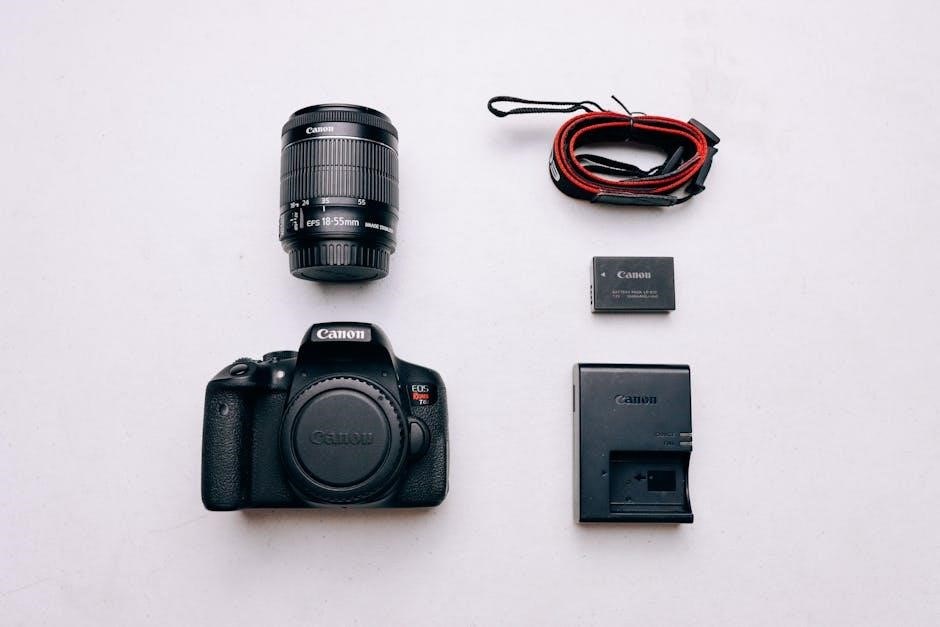
3․1 Unboxing and Initial Setup
Unboxing the Canon Digital Rebel XTi reveals the camera body, battery, charger, and manual․ Begin by charging the battery and inserting a memory card․ Familiarize yourself with the camera’s layout, including the mode dial, shutter button, and LCD screen․ The manual provides step-by-step guidance for initial setup, ensuring you understand basic operations and settings before capturing your first photos․ Proper setup ensures optimal performance and prepares you for exploring advanced features․
3․2 Charging the Battery and Inserting the Memory Card
Charge the battery using the provided charger until the indicator turns green․ Insert a compatible memory card (CF/SDHC) into the slot on the camera’s side․ Ensure the card is securely locked in place․ The manual provides detailed steps for these processes․ Properly charging and preparing your camera ensures it’s ready for use, allowing you to focus on capturing high-quality images without interruptions․
3․4 Basic Camera Controls and Layout
Familiarize yourself with the camera’s layout, including the mode dial, shutter button, and navigation buttons․ The LCD screen displays settings like ISO, white balance, and autofocus modes․ Use the control panel to adjust settings quickly․ The ergonomic design ensures easy access to essential functions, making it intuitive for both beginners and advanced users to operate the camera efficiently․
Shooting Modes on the Canon Digital Rebel XTi
The Canon Digital Rebel XTi offers various shooting modes, including Auto, Creative Zone (Av, Tv, M), and Custom modes, catering to both beginners and advanced photographers’ needs․
4․1 Auto Mode for Beginners
The Auto Mode on the Canon Digital Rebel XTi is designed to simplify photography for newcomers․ It automatically adjusts settings like exposure, focus, and white balance, ensuring sharp, well-lit images․ This mode is ideal for learning the basics, as it eliminates the need for manual adjustments․ With Auto Mode, beginners can focus on composition and creativity while the camera handles technical details, making it an excellent starting point for capturing high-quality photos effortlessly․
4․2 Creative Zone Modes (Av, Tv, M)
The Creative Zone Modes (Av, Tv, M) on the Canon Digital Rebel XTi offer advanced control for photographers seeking creative freedom․ Aperture Priority (Av) allows adjusting aperture to control depth of field, while Shutter Priority (Tv) lets you set shutter speed to freeze or blur motion․ Manual (M) mode provides full control over both aperture and shutter speed for precise results․ These modes are ideal for intermediate to advanced users looking to enhance their photography skills and achieve specific artistic effects․
4․3 Custom Modes (C1, C2, C3)
Custom Modes (C1, C2, C3) on the Canon Digital Rebel XTi allow users to save personalized camera settings for quick access․ Each mode can store unique configurations, such as aperture, shutter speed, white balance, and autofocus settings, tailored to specific shooting scenarios․ This feature enhances efficiency, enabling photographers to switch between setups effortlessly․ It’s ideal for those who frequently shoot in varying conditions or prefer consistent results without recalibrating settings each time, making it a versatile tool for both beginners and advanced users․
Custom Functions and Settings
Custom Functions on the Canon Digital Rebel XTi enable personalized camera settings, allowing users to tailor shooting preferences for enhanced creativity and efficiency in various photography scenarios․
5․1 Understanding Custom Functions
Custom Functions on the Canon Digital Rebel XTi allow users to personalize camera settings, enhancing creativity and efficiency․ These functions enable adjustments to autofocus, metering, and more, tailored to individual preferences․ By modifying default settings, photographers can optimize the camera for specific shooting styles or conditions․ The manual provides detailed explanations of each Custom Function, ensuring users can explore and implement these advanced features effectively to improve their photography experience․
5․2 Setting Up Custom Functions for Personalized Shooting
Setting up Custom Functions on the Canon Digital Rebel XTi enables photographers to tailor camera settings to their specific needs․ Users can adjust autofocus behavior, metering modes, and more to suit their shooting style․ The manual guides users through the process of selecting and configuring these functions, ensuring optimal performance in various scenarios․ By personalizing settings, photographers can enhance efficiency and achieve consistent, high-quality results in their work․

White Balance and Color Settings
This section explains the Canon Digital Rebel XTi’s white balance and color settings, helping users achieve accurate colors in various lighting conditions with options like Auto, Preset, and Manual modes․
6․1 Auto White Balance
The Canon Digital Rebel XTi’s Auto White Balance feature automatically adjusts color settings to match lighting conditions, ensuring accurate tones in images․ This mode is ideal for beginners or quick shooting scenarios, as it eliminates the need for manual adjustments․ The camera analyzes the scene and selects the most appropriate white balance, providing natural-looking results in various environments, from daylight to artificial light sources, with minimal user intervention required․
6․2 Preset White Balance Options
The Canon Digital Rebel XTi offers preset white balance options, including Daylight, Shade, Cloudy, Tungsten Light, White Fluorescent Light, and Flash․ These settings allow users to manually select the most appropriate white balance for specific lighting conditions, ensuring accurate color reproduction․ For example, Daylight mode is ideal for outdoor photography, while Tungsten Light is suited for indoor incandescent lighting․ These presets provide flexibility and control, enabling photographers to capture images with precise color accuracy in various environments without relying on the Auto mode․
6․3 Manual White Balance Adjustment
The Canon Digital Rebel XTi allows for manual white balance adjustment, enabling users to set a custom color temperature or use a reference object to achieve precise control over color accuracy․ This feature is particularly useful in unusual lighting conditions where preset options may not suffice․ By shooting a white object or inputting a specific Kelvin value, photographers can ensure their images reflect the true colors of the scene, enhancing overall image quality and creative control;
Using Lenses with the Canon Digital Rebel XTi
The Canon Digital Rebel XTi supports a wide range of EF-S and EF lenses, offering flexibility for various shooting scenarios․ Choose the right lens to enhance image quality and creativity, from kit lenses like the EF-S 18-55mm to specialized optics for specific needs, ensuring optimal performance in different conditions․
7;1 Compatible Lenses for the EOS System
The Canon Digital Rebel XTi is compatible with EF-S and EF lenses, offering versatility for various photography needs․ Popular options include the EF-S 18-55mm kit lens, prime lenses for portraits, and wide-angle or telephoto zooms for landscapes and wildlife․ The EF-S mount ensures optimal performance with Canon’s APS-C sensors, while EF lenses provide compatibility with full-frame cameras․ This extensive range allows photographers to choose the perfect lens for their creative vision․
7․2 Choosing the Right Lens for Different Shooting Scenarios
For various photography scenarios, the right lens is crucial․ Portraits shine with prime lenses like the EF 50mm f/1․8, offering shallow depth of field․ Landscapes and group shots benefit from wide-angle options such as the EF-S 10-22mm f/3․5-4․5․ Telephoto lenses like the EF 70-200mm excel for wildlife or distant subjects․ Matching the lens to the scene ensures optimal results, enhancing creativity and image quality․

Flash and Lighting with the Canon Digital Rebel XTi
Mastering flash and lighting enhances your photography․ The built-in flash provides convenience, while external options expand creativity․ Learn to balance light for stunning results in any condition․
8․1 Built-In Flash and External Flash Options
The Canon Digital Rebel XTi features a built-in flash for convenient lighting in low-light conditions․ It automatically pops up and fires based on scene brightness․ For more advanced lighting, external Speedlite flashes can be attached via the hot shoe, offering greater power and flexibility․ These external units allow for wireless operation, bounce flash, and higher flash synchronization speeds, enabling creative control over lighting setups for professional-grade results in various shooting scenarios․
8․2 Using Flash in Different Lighting Conditions
The Canon Digital Rebel XTi’s flash system excels in various lighting scenarios․ In low-light conditions, the built-in flash provides essential illumination, while fill flash helps balance shadows in bright settings․ For challenging lighting, the flash intensity can be manually adjusted․ External Speedlites offer wireless operation and bounce flash capabilities, allowing for more creative and natural lighting effects․ This versatility ensures optimal results, whether capturing portraits, indoor events, or outdoor scenes, making the XTi adaptable to diverse photographic situations․

Advanced Shooting Techniques
Explore advanced techniques like bracketing, HDR, and RAW shooting to enhance your photography skills with the Canon Digital Rebel XTi, guided by expert manual instructions․
9․1 Bracketing and HDR Photography
Bracketing allows capturing multiple exposures of a scene at different brightness levels, ideal for high dynamic range (HDR) photography․ The Canon Digital Rebel XTi supports Auto Exposure Bracketing (AEB), enabling up to three frames at +/- 2 stops․ This feature is perfect for landscapes and scenes with contrasting lights and shadows․ Combine bracketed images using software to create stunning HDR photos with enhanced detail and color accuracy, leveraging the camera’s RAW format for optimal results․
9․2 Shooting in RAW Format
Shooting in RAW format captures maximum image data, offering greater flexibility in post-processing․ Unlike JPEG, RAW files retain more detail, allowing adjustments to exposure, white balance, and color without quality loss․ This format is ideal for advanced photographers seeking precise control over their images․ The Canon Digital Rebel XTi supports RAW, enabling users to produce high-quality photos that can be finely tuned using Canon’s bundled software for optimal results․
9․3 Advanced Autofocus Techniques
The Canon Digital Rebel XTi’s 9-point autofocus system offers advanced techniques for precise subject tracking․ Users can customize AF point selection to suit their composition, ensuring sharp focus on moving subjects․ Continuous AF mode allows the camera to adjust focus as the subject moves, while AF lock freezes focus for recomposing shots․ These features enhance accuracy and flexibility, making the XTi ideal for capturing dynamic scenes with ease and professionalism․
Troubleshooting and Maintenance
Identify and resolve common issues with the XTi, such as sensor cleaning and error messages․ Regular maintenance ensures optimal performance and extends the camera’s lifespan effectively․
10․1 Common Issues and Solutions
Address common issues like error messages, sensor dust, and battery performance․ Solutions include restarting the camera, cleaning the sensor, and updating firmware․ Regular maintenance ensures reliability and image quality․
10․2 Cleaning the Sensor and Camera Maintenance
Regularly clean the sensor to prevent dust spots; Use a soft brush or blower for dry cleaning, and wet cleaning for stubborn spots․ Avoid harsh chemicals and scratch the sensor․ Clean the exterior with a microfiber cloth and mild soap solution․ Store the camera in a dry, cool place to prevent moisture damage․ Use the camera’s self-cleaning mode and avoid changing lenses in dusty environments to maintain optimal performance and image quality․

Post-Processing and Software
The Canon Digital Rebel XTi comes with bundled software for editing and enhancing photos․ Use Canon’s software to adjust settings, process RAW files, and improve image quality effortlessly․
11․1 Overview of Bundled Software
The Canon Digital Rebel XTi includes bundled software designed to enhance your photography workflow․ The software guide provides installation instructions and explains tools for image transfer, editing, and management․ Key features include RAW file processing, color correction, and photo organization․ The software supports both Mac and PC, offering compatibility for various operating systems․ It also enables advanced adjustments like noise reduction and sharpening, helping you achieve professional-grade results․ This comprehensive suite is essential for unlocking the full potential of your camera’s images․
11․2 Editing Photos with Canon Software
The Canon Digital Rebel XTi’s bundled software offers robust tools for editing photos; Users can adjust brightness, contrast, and color balance, as well as sharpen images and reduce noise․ The software supports RAW file processing, allowing for non-destructive editing․ Additional features include batch processing and customizable presets․ Compatible with both Mac and PC, the software provides an intuitive interface for enhancing photos․ Whether you’re a beginner or advanced user, these tools help refine your images and bring out their full potential․

Tips for Beginners
- Familiarize yourself with the camera’s layout and basic controls before shooting․
- Experiment with different modes to understand their effects on your photos․
- Review your shots on the LCD to learn and improve quickly․
- Practice regularly to master the camera’s features and settings․
12․1 Getting Familiar with the Camera
Start by understanding the camera’s layout, including the mode dial, shutter button, and LCD screen․ Experiment with different shooting modes to see how they affect your photos․ Review your images on the LCD to learn from your results․ Practice adjusting settings like aperture and shutter speed to gain confidence․ Familiarizing yourself with the camera’s features will help you capture better photos and make the most of its capabilities․
12․2 Best Practices for Shooting
Always review your camera settings before shooting to ensure they match your scene․ Use the appropriate shooting mode for your subject, such as Av for aperture control or Tv for shutter speed․ Check the LCD for image review and adjust settings as needed․ Experiment with angles and lighting to enhance composition․ Practice regularly to improve your skills and familiarity with the camera’s capabilities․ This will help you capture high-quality photos consistently․

Accessories for the Canon Digital Rebel XTi
Essential accessories include high-quality lenses, tripods, memory cards, and camera bags to enhance shooting experiences and protect your equipment for optimal performance and longevity․
13․1 Essential Accessories for Enhanced Shooting
Enhance your Canon Digital Rebel XTi experience with essential accessories like high-quality lenses, tripods, and memory cards․ The EF-S 18-55mm kit lens is a great starting point, but consider upgrading to other EF/EF-S lenses for versatility․ A sturdy tripod ensures sharp images in low light, while high-capacity memory cards allow for extended shooting sessions․ Additionally, an external flash and camera bag protect and complement your gear, ensuring optimal performance and creativity in various shooting scenarios․
The Canon Digital Rebel XTi manual is a valuable resource for mastering the camera, offering insights into key features, settings, and troubleshooting tips for enhanced photography experiences․
14․1 Summary of Key Points
The Canon Digital Rebel XTi manual provides a detailed guide to understanding and optimizing camera use․ It covers essential features like the 10․1MP sensor, 9-point autofocus, and 3fps shooting․ The manual also explores shooting modes, custom functions, and white balance settings․ Additionally, it offers insights into lens compatibility, flash usage, and advanced techniques such as HDR and RAW shooting․ Maintenance tips and troubleshooting solutions are included to ensure longevity and peak performance of the camera․ This comprehensive resource empowers users to unlock the full potential of their Digital Rebel XTi․
14․2 Final Thoughts on the Canon Digital Rebel XTi Manual
The Canon Digital Rebel XTi manual is an invaluable resource for photographers of all levels․ It provides a thorough understanding of the camera’s features, shooting modes, and customization options․ From basic controls to advanced techniques, the manual ensures users can maximize their camera’s potential․ Whether you’re a beginner or an experienced photographer, this guide helps you capture stunning images and explore the full capabilities of the XTi․ It’s a must-have for anyone serious about photography with this model․